Idea to DeviceCustom Electronics & Firmware Development

Home / Platform Capabilities

Display Controller & Embedded HMI Development Platform

DP video input and MIPI DSI / LVDS panel integration, integrated graphics acceleration, image rotation and scaling, and embedded touch interfaces, brought together on one display and interaction platform. If you already have a mature application direction in your industry, bring your requirements and we can assess the display and electronics together.

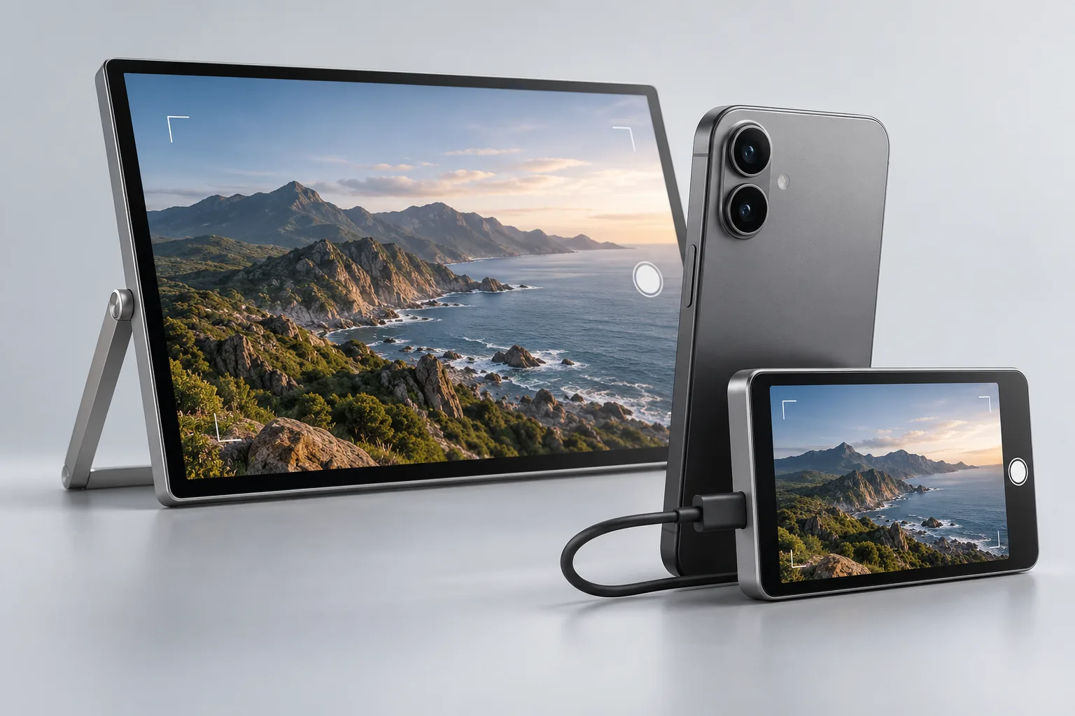
A landscape display and a small display showing the same camera feed at once, with a phone connected between them by a USB-C cable
Product Concept Illustration Multi-display evaluation direction · illustration, not a product photo

Platform specifications

Published capability modules, parameters and interfaces.

The table lists the platform's published parameters and interfaces by capability module, with the development value of each, so you can judge whether a direction is worth evaluating further.

Published capability modules, parameters and interfaces of the Display Controller & Embedded HMI Development Platform
Capability module Parameters & interfaces Development value
Control processing 300MHz 32-bit RISC-V with FPU / DSP extensions Can handle embedded control, display scheduling and interface logic; whether an external host processor is needed depends on application complexity and system architecture.
Video input DisplayPort (DP) 1.2 and eDP 1.4; EDID display identification; MST receive support Connects to DP sources such as phones and PCs. EDID lets the source identify the display capabilities of the panel. MST receive is a platform capability; whether more than one picture can actually be output depends on the source and is verified per project.
MIPI display output Dual MIPI DSI; D-PHY 1.2, DSI 1.2 / DCS 1.3; up to 4 lanes at 2.5Gbps per lane per interface; LVDS, QSPI and other panel interfaces Panel integration across sizes and resolutions, with panel initialization and timing confirmed per project. Dual-panel driving can be evaluated; panel timing, resource allocation and concurrent load are verified per project.
Display processing DPU; scaling, rotation, mirroring and layer composition For picture orientation, aspect-ratio conversion and multi-layer display layouts; the specific display path and load are verified per project.
Integrated Graphics Acceleration Integrated 2.5D GPU; path rendering, blending, 3×3 perspective transforms and color component reordering Supports evaluation of custom graphical interfaces, instrument graphics and graphics transforms for embedded HMI and touch panels; software integration and performance are assessed per project.
Image codec JPEG encoding and decoding Lightweight processing for image capture and display, and a technical consultation direction for image work.
Audio Dual I²S, 2-channel analog ADC, 6-channel DMIC, ASRC, VAD ASRC is asynchronous sample rate conversion, used to bridge clock domains running at different sample rates. VAD is voice activity detection, used to tell whether speech is present. Speech recognition, echo cancellation and translation are provided by you or an external platform.
Connectivity & control USB 3.1 Gen 1 / USB 2.0; I²C / SPI / UART Connects peripherals and control devices. A USB interface is a foundation, not a completed UVC / UAC / HID protocol stack; the protocol scope is confirmed per project.

Specific configuration, concurrency and performance are verified per project.

Technical Applications & Development Opportunities

Technical Applications & Development Opportunities.

We work with equipment manufacturers and engineering teams to evaluate custom controller boards, from video input and image processing to display output. The paths below describe target architectures. Data routing, software support and combined performance are verified for each project.

Implemented focus

Phone rear-camera monitors

Compact rear-camera monitors and livestream displays are the directions already brought up, and can go straight into solution evaluation.

Target Markets: Portable Monitors · Smartphone Camera Accessories · Instrument Displays

DP-to-MIPI DSI / LVDS Display Controller Boards

Partnership evaluation
Target path
Host DP output → Display & Image Processing Platform → MIPI DSI / LVDS panel.
Use cases
Connect DP video from a computer, industrial PC or compatible mobile device to a bare display panel. Suitable directions include portable monitors, rear-camera companion displays, instrument secondary displays and embedded display modules.
Capabilities to evaluate
DP 1.2 / eDP 1.4 input; MIPI DSI / LVDS output; scaling, mirroring, rotation, gamma adjustment and OSD layer overlays.
Integration value
Combine video reception, selected image processing and display control on a common platform, with board layout, connectors and panel integration tailored to the product.
Design considerations
USB-C requires a compatible DP Alt Mode connection and negotiation design. Touch requires a touch controller and a return path. The platform does not provide native HDMI input.

Target Markets: Test & Measurement Instruments · Equipment Control Panels · Display Modules

MIPI DSI Host-to-LVDS Panel Integration

Partnership evaluation
Target path
Main processor MIPI DSI output → Display & Image Processing Platform → LVDS panel.
Use cases
Evaluate integrated DSI reception, image processing and LVDS output when the processor and target panel use different interfaces. Suitable directions include instruments, equipment control panels and display upgrades.
Capabilities to evaluate
MIPI DSI reception, multiple LVDS channel configurations, input/output size adaptation, orientation changes and status overlays.
Integration value
Suitable when a design needs both interface adaptation and image processing. For interface conversion alone, compare cost and complexity with dedicated bridge devices.
Design considerations
Confirm the DSI operating mode, LVDS mapping, pixel clock and complete data path.

Target Markets: Digital Microscopes · Soldering Inspection · Manual Visual Inspection

Local Camera Preview with Graphics Overlays

Partnership evaluation
Target path
Camera with integrated ISP → MIPI CSI → Image processing / DPU → DSI / LVDS panel.
Use cases
Evaluate standalone viewing boards for digital microscopes, soldering observation systems and manual inspection terminals.
Capabilities to evaluate
The camera performs ISP processing and provides a compatible pixel format. Evaluate scaling, mirroring, rotation and display composition on the platform. The integrated 2.5D GPU can support crosshairs, reference outlines and controls, while the DPU handles display layer blending. JPEG encoding can be evaluated for snapshots and image records.
Integration value
Combine a local camera view, reference graphics and user controls in one display terminal.
Design considerations
Verify CSI data types, sustained frame rate, frame buffering and concurrent display/JPEG operation. Image recording requires storage and software integration. Sensor ISP and automated defect detection algorithms are outside this scope.

Target Markets: Industrial Inspection Scopes · Equipment Interior Inspection · Wide-Angle Viewing Devices

Wide-Angle Camera Dewarping for Local Displays

Partnership evaluation
Target path
Wide-angle camera with integrated ISP → MIPI CSI → Dewarp processing → Display output.
Use cases
Evaluate lens geometry correction before display for industrial inspection scopes, equipment interior viewing and dedicated wide-angle imaging terminals.
Capabilities to evaluate
Radial, tangential, fisheye and perspective-related transforms with bilinear interpolation, combined with orientation adjustment, overlays and user controls.
Integration value
Evaluate replacing fixed geometry transforms and selected display processing logic in an existing FPGA design.
Design considerations
Confirm calibration models, maximum processing dimensions, throughput and latency. Geometry correction does not guarantee measurement accuracy. Long-distance probe transmission requires a separate design.

Target Markets: Dual-Display Instruments · Main/Secondary Display Terminals · Dual-Window Display Devices

Dual-Display Modules from a Single DP Connection

Partnership evaluation
Target path
Host DP MST output → Two display paths → Two display panels.
Use cases
Evaluate reception of two video streams over one DP connection for dual instruments, dual-window displays and dedicated two-screen devices.
Capabilities to evaluate
Two-stream DP MST reception, two main video paths, dual MIPI display outputs and multiple LVDS configurations.
Integration value
Evaluate a centralized dual-display controller board instead of separate display control designs.
Design considerations
The host must support the required MST mode. Verify both panels' resolutions, refresh rates, output combinations and bandwidth allocation. This is not two live video inputs composited onto one panel, and does not imply dual independent pictures from every phone.

Target Markets: FPGA-Based Video Devices · Image Processing Boards · Custom Display Terminals

Fixed-Function FPGA Image Processing Replacement Assessment

Partnership evaluation
Target processing section
Compatible video input → Scaling / rotation / dewarping / layer composition → Compatible output.
Use cases
Evaluate dedicated processing blocks for selected fixed image transforms and display control functions currently implemented in an FPGA.
Integration value
Compare component count, board complexity, software effort and cost for each function. Full FPGA replacement and a fixed cost reduction are not assumed.
Design considerations
Review every responsibility of the existing FPGA. Sensor ISP, special interfaces, precision triggering/synchronization and custom inspection algorithms are outside the confirmed replacement scope.

The paths above are target architectures, not off-the-shelf solutions or production capabilities. Feasibility, effort and delivery scope are evaluated per project.

Function mapping

Existing functions and platform blocks.

Fixed processing functions in an existing FPGA design can be compared block by block against the platform's modules, to judge which parts are worth evaluating further.

Mapping between existing FPGA functions and platform blocks
Existing function Platform block
Video scaling Dedicated scaling blocks
90°/270° rotation and mirroring Dedicated rotation and mirroring block
Lens distortion and perspective correction Dewarp
Graphics, outlines and UI rendering 2.5D GPU
Display layer blending and color conversion DPU
Local panel output MIPI DSI / LVDS / QSPI

Engineering selection considerations

Block-level specifications that affect selection.

The table lists published specifications and directional constraints for each processing block, to judge whether a path is feasible and what has to be confirmed first.

Published specifications and directional constraints for each processing block
Item Selection note
MIPI reception Two receivers, each up to 4 lanes at 2.5Gbps per lane. Link rate is not end-to-end processing throughput.
Dedicated scaling Maximum active input line width of 2800 pixels for the dedicated scaling block.
Dedicated rotation Maximum active output line width: RGB888/YUV444 ≤1600; YUV422 ≤2400; YUV420 ≤3200 pixels.
Display composition The main display lists four layers at both front and back stages, with a background layer at the back stage; the secondary display lists two layers plus background. Confirm the selected path; the stages are not added together into a promised total layer count.
JPEG 8-bit pixels. Sustained encoding/decoding throughput and concurrent operation require verification.
Camera front end The camera architectures described here require a compatible camera with integrated ISP or an external ISP.
Interface direction DP is an input. MIPI TX is a DSI display output and is not presented as a CSI camera output.
Unverified paths CSI-to-USB and composition of two live video inputs onto one panel are not presented as verified functions.

These are block-level specifications, not guaranteed maxima for every combined processing path. The rotation line width is a limit of one processing block, not a platform-wide maximum resolution.

Engineering inquiry

Bring your video processing requirements.

The details below help us assess faster. Incomplete information is fine to start with.

  1. Input device and format
  2. Required processing
  3. Output interface and panel
  4. Resolution and frame rate
  5. Latency target
  6. Existing FPGA or bridge design
Discuss Your Video Processing Requirements

How we work together

Three ways to collaborate.

Your industry experience plus our display and electronics development is usually more efficient than either side working alone. Which route to choose depends on your team and project stage.

We develop

We complete the display, electronics and firmware and deliver a PCBA or reference design within the agreed scope.

Joint development

You handle the application, algorithms or the complete device; we handle the display and electronics, advancing together by division of work.

You develop

You complete product development yourself; we provide materials and support within the agreed scope.

Delivered materials, firmware, tools and licensing scope are agreed per project.

Next step

Talk about the application first, then judge whether the platform fits.

Tell us your application direction, target form and existing foundation, and we will explain which parts can be evaluated directly and which need validation first.

Contact us

Share a reference product or your design idea.

Let's discuss the electronics behind it.

Useful details: a reference product, your use case, size preference, project stage or expected volume. Incomplete specifications are fine.

WhatsApp QR code
WhatsApp

Scan to connect on WhatsApp.

Email sales@ideatodevice.com